


In semiconductor manufacturing and FPD (Flat Panel Display) panel production, the preparation of thin films is a crucial process.
There are various methods for preparing thin films (TF, Thin Film), among which two are commonly used:
CVD (Chemical Vapor Deposition): Chemical vapor deposition
PVD (Physical Vapor Deposition): Physical vapor deposition
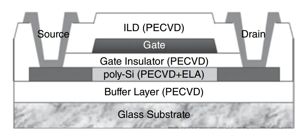
Among them, the buffer layer, active layer, and insulating layer are all deposited using the PECVD method within the chamber of the equipment.
Special gases such as SiH4/NH3/N2O are used for the deposition of SiN and Si/SiO2 thin films.
Some CVD equipment requires the use of H2 for hydrogenation to increase carrier mobility.
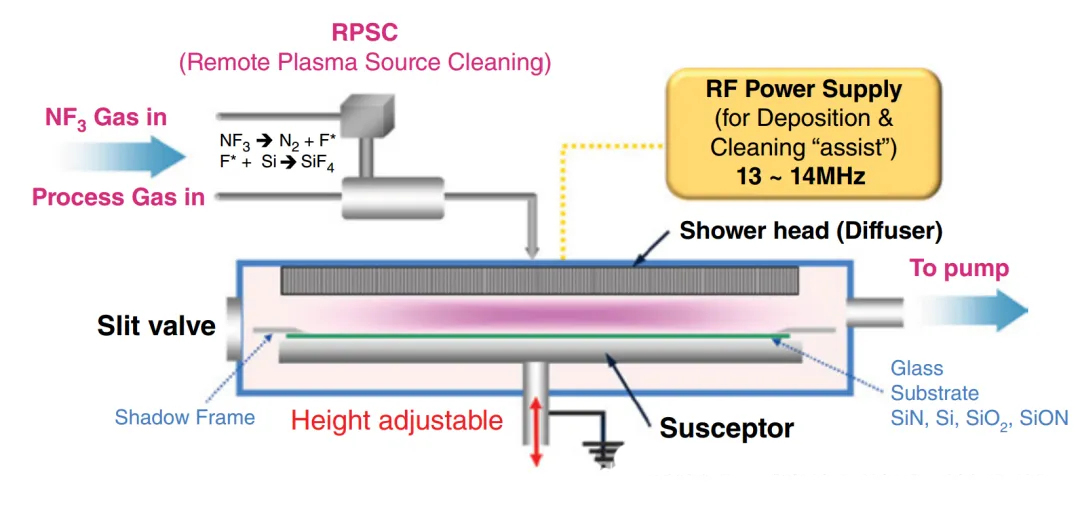
NF3 is used as a cleaning gas. In comparison, F2 is highly toxic, and SF6 has a higher greenhouse effect than NF3.
In semiconductor device processes, there are even more types of thin films, in addition to the common SiO2/Si/SiN,
including W, Ti/TiN, HfO2, SiC, and so on.
This is also the reason why there are a variety of precursors for advanced materials used in the semiconductor industry, in order to produce various types of thin films.

We will explain in the following manner:
1. Types of CVD and Some Precursor Gases
o CVD is a broad concept that can be divided into many types.
o Common types include:
(Note: The translation continues from here, providing a framework for the subsequent sections.)
(Translation of the introduced section and the beginning of the first point:)
We will proceed with the explanation as follows:
1. Types of CVD and Some Precursor Gases
CVD stands for Chemical Vapor Deposition, which is a general term encompassing various types.
Commonly seen types are:
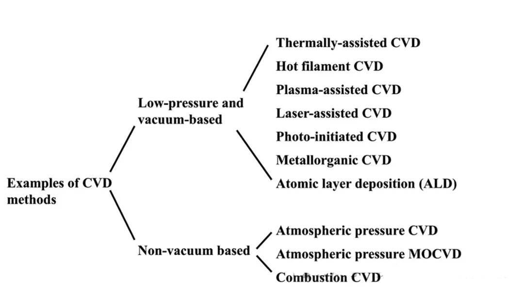
ECVD: Plasma Enhanced CVD
LPCVD: Low Pressure CVD
ALD: Atomic Layer Deposition
MOCVD: Metal-organic CVD
In the process of CVD, the chemical bonds of the precursors need to be broken before undergoing chemical reactions.
The energy required to break the chemical bonds comes from heat, which results in a relatively high chamber temperature. This can be unfavorable for certain processes, such as those involving substrate glass for panels or PI materials for flexible screens. Therefore, by inputting other forms of energy (such as generating plasma), the process temperature can be lowered to meet the requirements of temperature-sensitive processes, and the thermal budget can also be reduced.
As a result, the PECVD method is widely used in the FPD display industry for depositing a-Si:H/SiN/poly-Si.
Common precursors and thin films in CVD:
Polysilicon/monocrystalline silicon, SiO2, SiN/SiON, W/Ti, WSi2, HfO2/SiC.
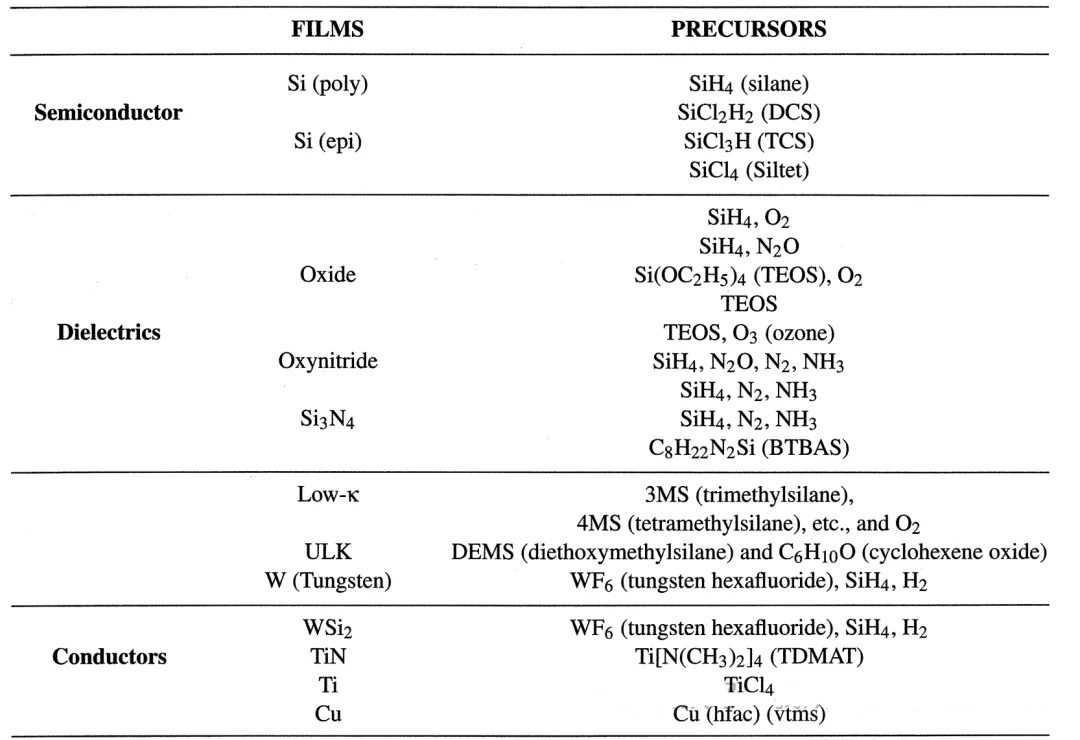
Due to the wide variety of reaction precursors in CVD, some of which have very complex molecular formulas, we often encounter abbreviations. Here is a summary of some of these abbreviations:
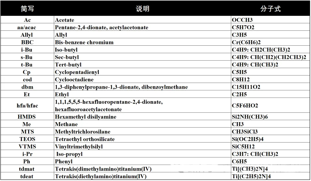
Precursors for the reaction of common thin films:
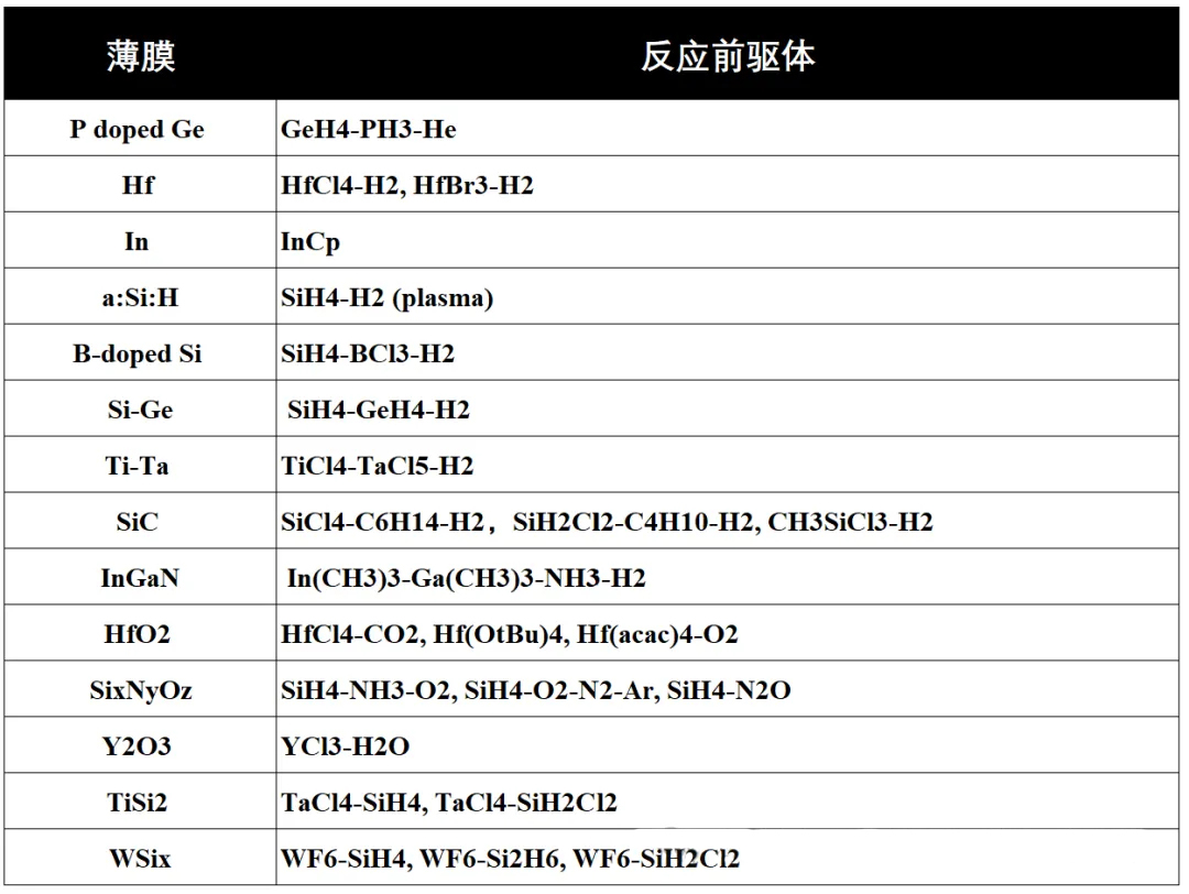
The selection of these chemical reaction gases is carefully considered based on the following criteria:
1. Feasibility: The chemical reaction must be able to occur under appropriate conditions. The direction and extent of the reaction can be determined by calculating the sign of the change in Gibbs free energy under the appropriate conditions.
2. Reaction rate: The rate of the chemical reaction is another consideration. The reaction rate should be controllable, neither too slow nor too fast. Thermodynamics addresses the issue of feasibility, while kinetics addresses the issue of rate. These are the most basic considerations. In the design of a CVD reactor, there are also gas transport processes and adsorption processes, which can affect the overall deposition rate of the thin film (A/min).
A PECVD recipe for the deposition of SiO2:
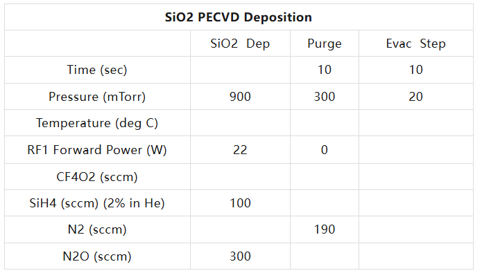
CF4/O2 is used for cleaning the chamber (Cleaning) during the deposition of SiN, and N2O can be replaced with NH3.
Basic mechanism of CVD:
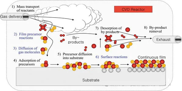
Basic steps:
1. Reaction precursor gases enter the chamber.
2. Intermediate products are generated through gas reactions.
3. The intermediate gas products diffuse to the substrate surface.
4. They adsorb onto the substrate surface and diffuse.
5. Chemical reactions occur on the substrate surface, leading to nucleation/island formation/film formation.
6. By-products desorb and are pumped away by the vacuum pump, then processed and discharged through the scrubber.
As mentioned earlier, the entire process consists of multiple steps including diffusion, adsorption, and reaction. The overall film deposition rate is influenced by many factors, such as temperature, pressure, type of reaction gases, and type of substrate.
Diffusion can be predicted using diffusion models, adsorption has its theories, and chemical reactions have reaction kinetics theories.
Throughout the process, the slowest step determines the overall reaction rate. This is similar to the critical path method in project management, where the longest sequence of activities determines the shortest project duration, and the duration of this path can be shortened by allocating resources.
Similarly, in CVD, by understanding the entire process and identifying the key bottleneck limiting the film deposition rate, parameters can be adjusted to achieve the desired deposition rate.
Evaluation of CVD Film Quality
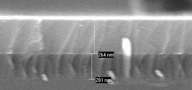
Deposition of a-Si on SiO2
Some films are planar, some fill holes, and some fill trenches, each serving different functions.
Commercial CVD equipment must meet basic requirements:
1. Throughput and deposition rate of the equipment
2. Consistency
3. The gas-phase reaction must not produce particles; it is crucial that no particles are generated in the gas phase.
Other evaluation criteria include:
· Good step coverage
· Ability to fill high aspect ratio gaps (conformality)
· Good thickness uniformity
· High purity and density
· High degree of structural perfection with low film stress
· Good electrical properties
· Excellent adhesion to the substrate material
Basic supporting systems for CVD operation
Currently, many commercial CVD processes are carried out in a vacuum environment, so let's understand some basics of vacuum technology and fundamental theories of gases.
1. Vacuum
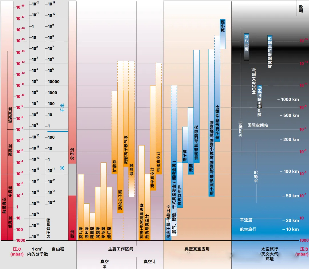
Based on different pressures, we classify vacuums into several types: low vacuum, medium vacuum, high vacuum, and ultra-high vacuum, with the pressure gradually decreasing to the Torr level.
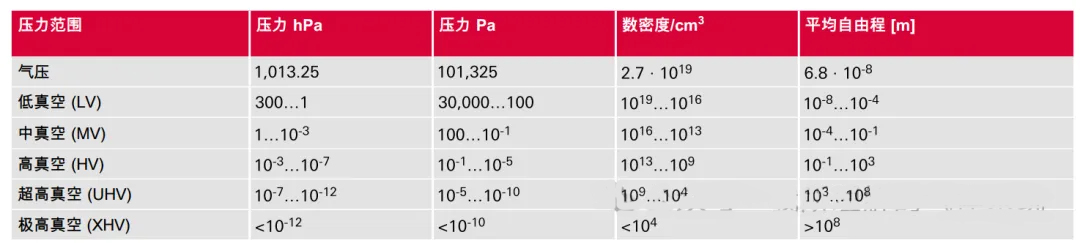
Although the classification of vacuums may seem arbitrary, the flow behavior at different pressures varies significantly, and the corresponding theories are completely different. At low vacuum levels, the flow may be viscous, while at high vacuums, it may be molecular. When the pressure is very low, it conforms to the definition of an ideal gas, which is a very important foundation.
Here, we need to review the ideal gas equation of state, PV=RT. When P is very small, V is very large, indicating that the molecular density is low, and the spacing between molecules is large, leading to a long mean free path between molecules, which is intuitive.
For a system, how is vacuum achieved? This requires a vacuum pump. There are two main types of vacuum pumps: gas transfer and gas trapping.
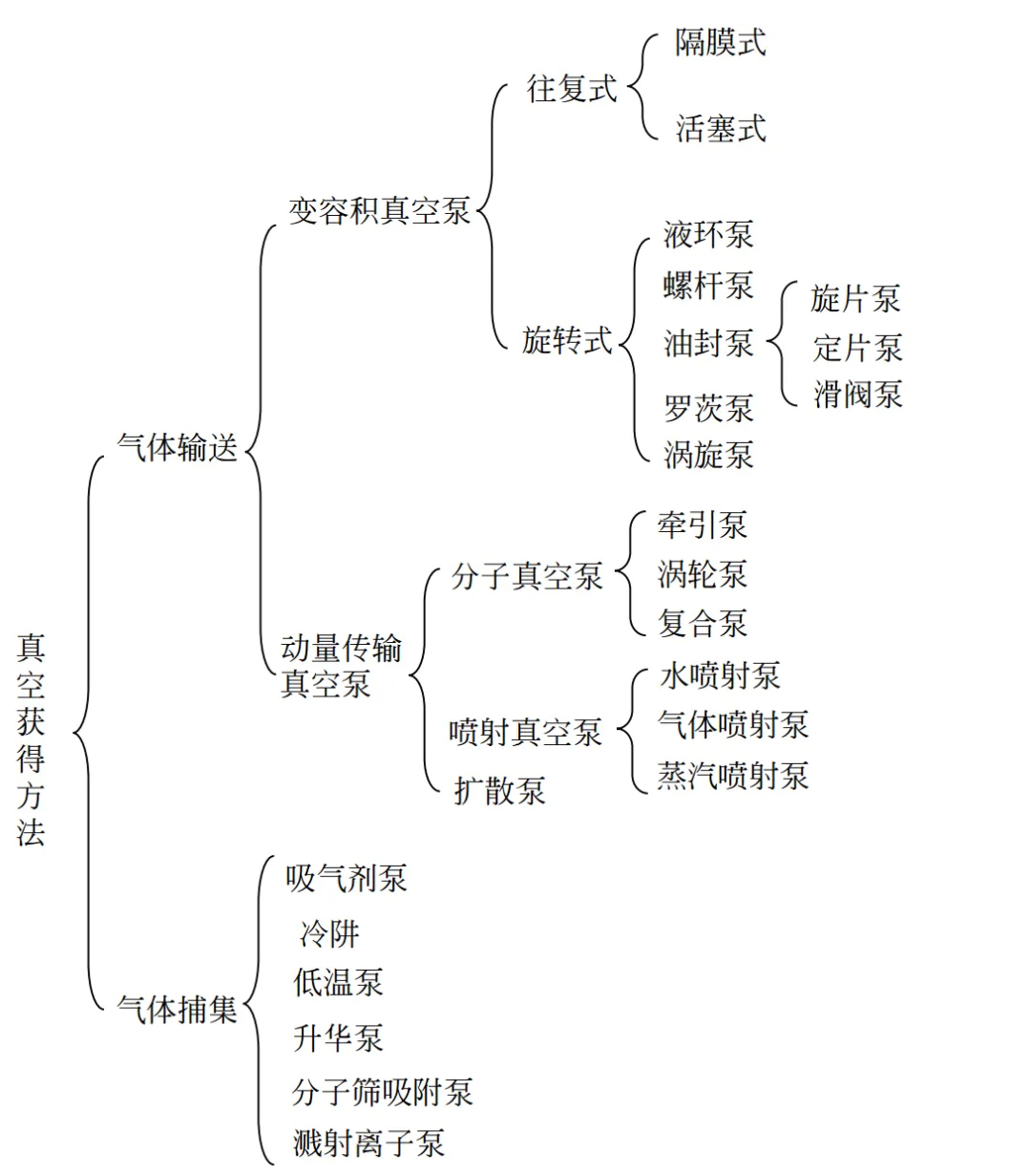
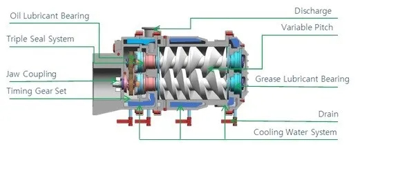
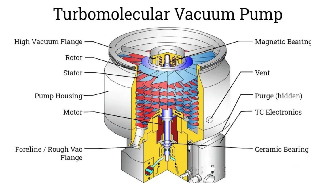
We often hear about Roots pumps, screw pumps, and molecular pumps as types of vacuum pumps.
The basic parameters of a vacuum pump include the inlet pumping speed in m³/s, the inlet gas flow rate in Pa·m³/s, the ultimate pressure, and the base pressure.
Relying solely on the vacuum pump is not enough for the entire system; other factors must also cooperate with the vacuum pump:
Condensation and evaporation of water molecules on the system piping or walls, desorption (gas molecules adsorbing onto the walls), diffusion, permeation, and leaks can all cause the vacuum level to rise. Generally speaking, sealing and high temperature (high-temperature heating of the pumping line) can effectively avoid these issues.
In a vacuum system, the unit of gas flow rate requires special explanation: A dimensional analysis shows that Pa·m³/s = N·m/s = J/s = W, which is a unit of energy. Since the product of pressure (P) and volume (V) for an ideal gas is related to temperature and molecular density, this quantity represents the number of molecules flowing.
Analyzing a typical vacuum pumping system:
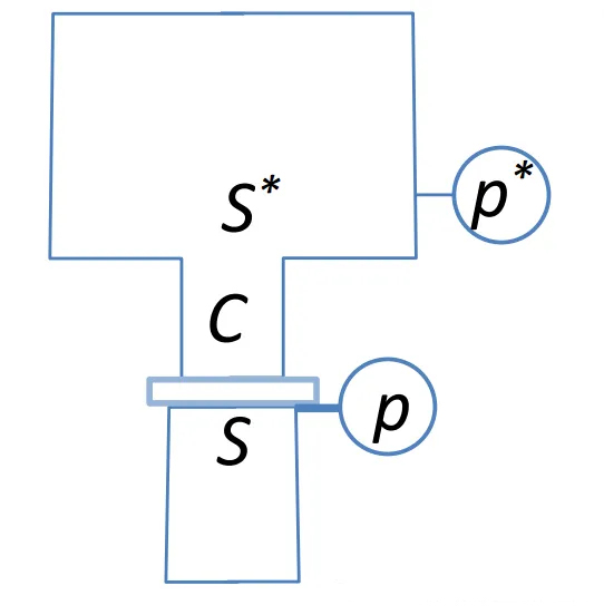
The inlet pressure of the vacuum pump is P, and the pumping speed is S. The pump is connected to a container through a pipeline, with the outlet pressure of the container being P* and the outlet pumping speed being S*, which is also known as the effective pumping speed and is the parameter we are most interested in.
When the system reaches a steady state, the gas flow rate at each point is equal (mass conservation).
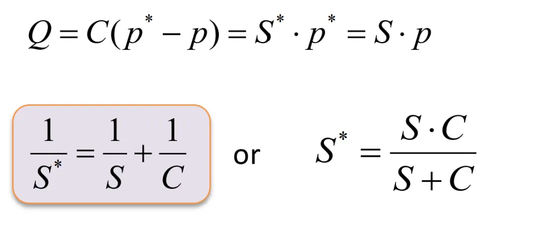
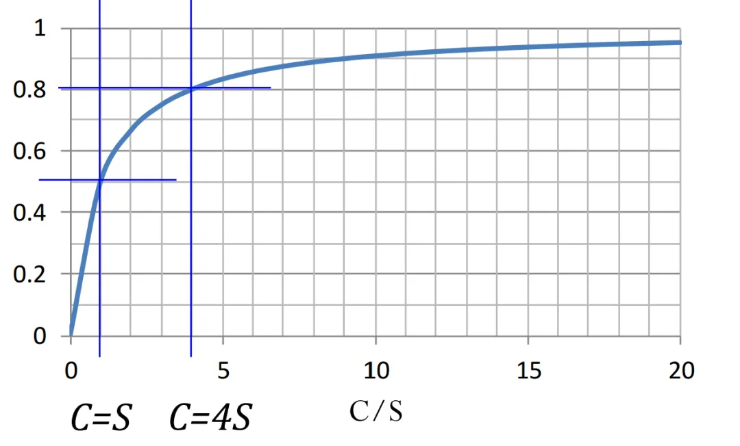
When the conductance C of the pipeline is equal to the pumping speed, the efficiency is only 50%. The higher the conductance of the pipeline, the better. Otherwise, even if a vacuum pump with a high pumping speed is used, if the connected pipeline has a low conductance, the efficiency will still be low. The conductance of a circular pipe can be calculated as follows:
From a qualitative perspective, vacuum piping connections should have a large diameter (d) and be short in length (L), i.e., short and thick, with the conductance being as large as possible. Therefore, the pumping line should have few and short elbows, and the pipe diameter should be sufficiently large to improve the efficiency of the corresponding vacuum pump.
For helium leak detection in long vacuum pipelines, the pressure distribution follows a parabolic pattern. The pressure drops more slowly at the far end of the pipeline and drops more rapidly as it approaches the vacuum pump.
Another concern of ours is: for a sealed space (with very little leakage), how long will it take to pump down to our desired pressure Pw?
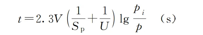
We can calculate the following example using:
· The volume of the container V, in liters (L)
· The pumping speed of the vacuum pump S, in liters per second (L/s)
· The initial pressure P and the pressure at time t, Pi, in pascals (Pa)
Example calculation:
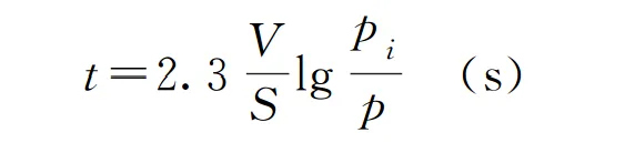
Equipment volume: 2 m³, equipped with a vacuum pump with a pumping speed of 80 m³/h. Calculate the time t required to pump down from atmospheric pressure to 1000 Pa.
t = 2.3 * 2000 / (80 * 1000) / 60 * lg(100000 / 1000) = 4.6 * 1.5 = 6.9 minutes
Given the volume, required time, and pressure, we can also calculate the pumping speed to select the appropriate pump.
Note:
Not all vacuum situations can be simply calculated and selected in this way. This formula has certain premises.
It applies to high-conductance piping systems with viscous flow, and not to very rarefied high-vacuum conditions.
With a vacuum pump, how will process gases behave under low vacuum conditions?
Gases can be considered as ideal gases under low vacuum conditions where the spacing between molecules increases. We want to know:
1. What is the microscopic velocity distribution of these rarefied gas molecules?
2. What is the collision behavior of these rarefied gas molecules?
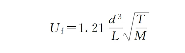
3. What is the flow rate of these rarefied gas molecules across a cross-section (flux J, in kg/m²/s)?
Whether it's CVD or PVD (evaporation or sputtering), understanding these three questions is crucial because they are closely related to the deposition rate.
If we take the cross-section as a wafer or glass substrate, knowing the flux tells us how many molecules collide with the wafer per second. Only those that reach the wafer can potentially contribute to film formation, so this value sets an upper limit.
4. What is the microscopic velocity distribution of these rarefied gas molecules?
The Maxwell-Boltzmann velocity distribution function for ideal gases:
He is present in thermodynamics, statistical mechanics, and even more so, he is a master of electromagnetism.
He is ubiquitous in physics.
Let's state the conclusion first, and then proceed with the derivation.
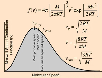
The velocities of rarefied gas molecules follow a distribution, so they do not have a uniform speed. Some molecules move faster, while others move slower; it's a statistically averaged property.
There are three velocities of interest to us: the most probable speed (vp), the average speed (V), and the root-mean-square speed (Vrms).
Among these, the average speed is what we will use later.
All three speeds are only related to temperature and the molecular weight of the gas. Why are they independent of pressure? The reason is that we have assumed an ideal gas at infinitely low pressure.
Maxwell distribution for H2 gas:
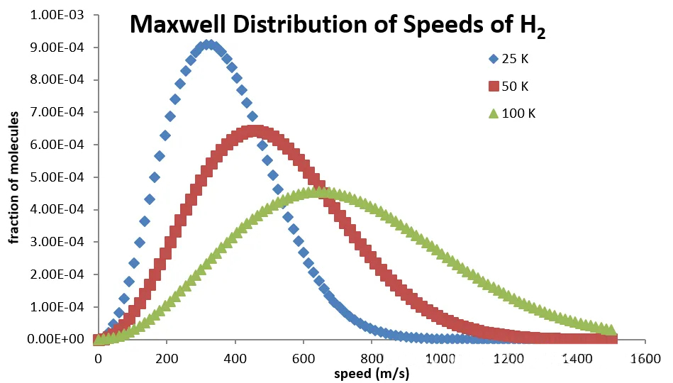
At 100K (-173°C), the velocities of H2 molecules are concentrated around 800 m/s. If the temperature rises to room temperature, the value can reach 2000 m/s.
This conclusion might be mind-blowing. So why don't we perceive the flow of H2 to be like this? It's because H2 molecules constantly collide with each other in space.
We want to know, for a specific molecular density n, what is the flux of molecules colliding perpendicularly with a cross-section at the average speed? Half of the molecules have the opposite velocity, so we need to multiply by 1/2. Since the velocity has components in all directions, we average them out and multiply by 1/2 again.
Ultimately, we get: J = 1/4 * n * V (average).
In the next article, we will try our best to derive the Maxwell speed distribution, as it is extremely important.
2. What is the collision behavior of these rarefied gas molecules like?
This is related to what we commonly refer to as the mean free path.
Calculation of the mean free path:
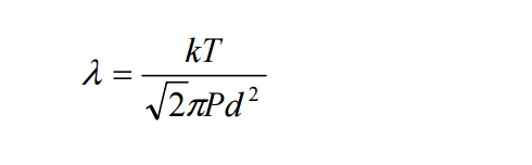

We can determine whether the flow regime is molecular by comparing the mean free path with the dimensions of the chamber.
In the next article, we will specifically explain the derivation of the velocity distribution, the mean free path, and gas measurement (the use of Slpm).
We will then proceed to a simple analysis of thermodynamics and kinetics, and discuss some thin film deposition processes, particularly the commonly used Si/SiO2/SiN and W.


