


Turning
Turning is primarily conducted on a lathe, where a cutting tool is used to machine a rotating workpiece. Drills, reamers, taps, dies, knurling tools, and other tools can also be employed on the lathe for corresponding operations. The principle of turning involves the rotation of the workpiece (primary motion) and the linear or curvilinear movement of the turning tool within a plane (feed motion). This process can be used to machine internal and external cylindrical surfaces, end faces, conical surfaces, formed surfaces, and threads. When turning a cylindrical surface, the turning tool moves parallel to the workpiece's rotational axis. When facing or cutting off the workpiece, the tool moves horizontally perpendicular to the rotational axis. If the tool's movement forms an oblique angle with the workpiece's rotational axis, a conical surface can be machined.
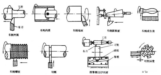
The main parameters in turning are the depth of cut and the feed rate. The depth of cut refers to the maximum dimension of the cutting layer perpendicular to the feed direction, typically the vertical distance between the machined and unmachined surfaces of the workpiece. The feed rate is the relative displacement of the workpiece or tool in the feed direction per revolution or reciprocation of the workpiece (or tool), or per tooth of the rotating tool. In rough turning, larger depths of cut and feed rates are used to enhance productivity, while in finish turning, smaller depths of cut and feed rates are selected to ensure the required machining accuracy and surface quality of the workpiece.
Milling
Milling operates in the opposite manner to turning, utilizing a rotating multi-tooth cutter to machine the workpiece, making it a highly efficient machining method. During milling, the cutter rotates (primary motion), and the workpiece moves (feed motion). The workpiece can also be fixed, but in this case, the rotating cutter must move, performing both the primary and feed motions simultaneously. Milling is typically performed on milling machines or boring machines and is suitable for machining planes, grooves, various formed surfaces such as splines, gears, threads, and special mold surfaces.
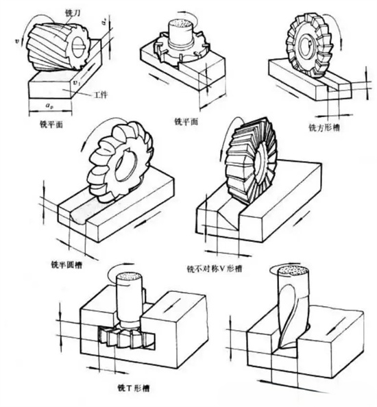
The characteristic of milling is that each tooth of the cutter intermittently cuts the workpiece, with the cutting thickness varying during each tooth's engagement. The feed per tooth represents the relative displacement of the workpiece within the time it takes for the cutter to rotate past one tooth.
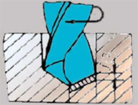
Drilling
Drilling is the basic method for machining holes, usually performed on drilling machines or lathes, and can also be done on boring or milling machines. During drilling, the drilling tool and the workpiece rotate relative to each other (primary motion) and move axially (feed motion). Due to its relatively low precision, drilling is mainly used for rough machining or as a pre-machining step before finish machining.
Grinding
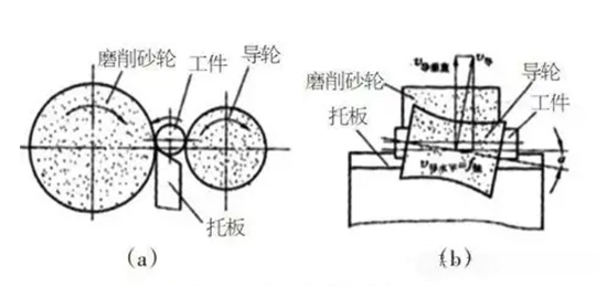
Grinding involves using a high-speed rotating abrasive tool, such as a grinding wheel, to machine the surface of a workpiece. Grinding is classified as a finishing operation in machining, with small material removal and high precision. It is used to machine internal and external cylindrical surfaces, conical surfaces, planes, threads, splines, gears, and other special or complex formed surfaces of workpieces. Due to the high hardness of the abrasive grains and the self-sharpening property of the grinding tool, grinding can be used to machine various materials, including hardened steel, alloy steels, carbides, glass, ceramics, and marble. Grinding is divided into external cylindrical grinding, internal cylindrical grinding, surface grinding, and centerless grinding. External cylindrical grinding is mainly performed on external cylindrical grinding machines to grind the outer cylinders of shaft-type workpieces. Internal cylindrical grinding is mainly performed on internal cylindrical grinding machines, universal cylindrical grinding machines, or jig grinding machines to grind cylindrical holes, conical holes, and hole end faces of workpieces. Surface grinding is mainly performed on surface grinding machines to grind planes and grooves. Centerless grinding is performed on centerless grinding machines to grind the outer cylinders of workpieces without using centers for centering and supporting; instead, the workpiece is placed between the grinding wheel and the guide wheel, supported by a lower rest, and driven to rotate by the guide wheel.
Grinding operates at high speeds and temperatures, enabling it to achieve high precision and very low surface roughness. It can machine not only soft materials like unhardened steel, cast iron, and non-ferrous metals but also hard materials that cannot be machined by other tools, such as ceramics and carbides. The cutting depth in grinding is very small, and the amount of metal removed in a single pass is minimal. During grinding, a large amount of fine grinding dust is ejected from the grinding wheel, and metal chips are ejected from the workpiece, posing a risk of injury to personnel.
Planing
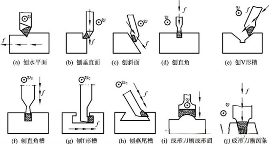
Planing involves the relative linear reciprocating motion between a planing tool and a workpiece, making it one of the primary methods for machining planes. It is suitable for single-piece and small-batch production of planes, vertical surfaces, and inclined surfaces. Planing can be performed on shaper machines or planer machines, with the primary motion being a variable-speed reciprocating linear motion. Due to inertia during speed changes, the cutting speed is limited, and no cutting occurs during the return stroke, resulting in low efficiency and unsuitability for mass production. Planing can also be widely applied to machining straight slots, dovetail slots, T-slots, racks, gears, splines, and formed surfaces with straight generatrices. Its characteristics include good versatility, low efficiency, and moderate precision.
Boring
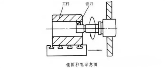
Boring is a turning process that uses a tool to enlarge the internal diameter of a hole or other circular profile. The boring tool rotates as the primary motion, and the boring tool or workpiece performs the feed motion. Boring is typically performed on boring machines, machining centers, or combination machines. It is mainly used to machine cylindrical holes, threaded holes, internal grooves, or end faces on workpieces such as boxes, brackets, and bases. When special attachments are used, it can also machine internal and external spherical surfaces, conical holes, etc. During boring, the workpiece is mounted on the machine table or fixture, and the boring tool is clamped on the boring bar (or can be integrated with it), driven to rotate by the spindle. Boring applications generally range from semi-rough to finish machining. Boring tools are classified into single-edge, double-edge, and multi-edge boring tools, with single-edge boring tools being the most commonly used.
Broaching
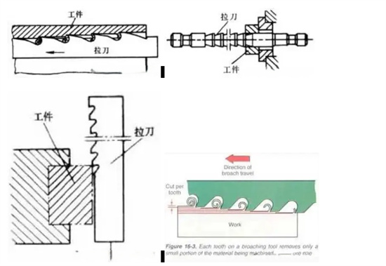
Broaching is a cutting process that uses a broaching machine (broach) to machine the internal and external surfaces of a workpiece. The broach moves axially under tension to machine the workpiece's internal or external surfaces. Unlike other cutting operations, broaching primarily considers tool wear and tool life. During broaching, multiple teeth engage simultaneously, and the cutting width is often large, making chip removal difficult. Therefore, low-viscosity oils are commonly required. Broaching is divided into internal broaching and external broaching. Internal broaching is used to machine various shaped through-holes or internal through-slots, such as round holes, square holes, polygonal holes, spline holes, keyway holes, internal gears, etc. Before broaching, a pre-machined hole is required for the broach to be inserted. Generally, the diameter range of broached holes is 8–125 mm, and the depth cannot exceed five times the hole diameter range. External broaching is used to machine non-closed surfaces, such as planes, formed surfaces, grooves, tenons, blade tenons, and external gears.
It is particularly suitable for mass production of relatively large planes and composite formed surfaces, such as cylinder blocks, bearing seats, and connecting rods. Broaching offers advantages such as high efficiency, high precision, a wide range of applications, and simple structure and operation. However, it also has disadvantages, including complex tool structures and high costs. During broaching, the sequence and method of removing the machining allowance from the workpiece include form broaching, progressive broaching, wheel broaching, and combined wheel broaching. Form broaching offers high precision and low surface roughness but low efficiency and longer broach lengths, mainly used for machining small to medium-sized round holes and formed surfaces with high precision requirements. Progressive broaching is suitable for rough broaching of complex machined surfaces, such as square holes, polygonal holes, and spline holes.
This method uses easier-to-manufacture broaches but results in poorer surface quality. Wheel broaching offers high cutting efficiency and can reduce broach length but results in poor surface quality, mainly used for machining round holes with larger sizes, larger machining allowances, and lower precision requirements. Combined wheel broaching combines the advantages of wheel broaching for rough machining and form broaching for finish machining, widely used in round hole broaching.
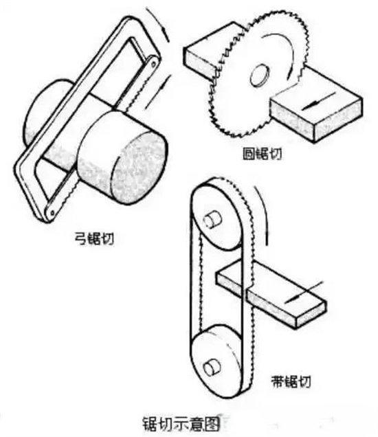
Sawing
Sawing involves using a cutting tool with many teeth along its edge (such as a saw blade, circular saw blade, or saw band) or a thin abrasive wheel to cut a narrow slot or separate a workpiece or material. Sawing can be classified into bow sawing, circular sawing, band sawing, and abrasive wheel sawing based on the type of tool used. Bow sawing involves tensioning a saw blade on a bow-shaped saw frame and performing a linear reciprocating motion to cut the workpiece. It is typically performed on bow sawing machines using power or manually. Due to the non-cutting motion during the return stroke, bow sawing has low efficiency. Circular sawing involves rotating a circular saw blade driven by a spindle on a circular sawing machine to continuously cut the workpiece, offering high efficiency. Band sawing involves using two wheels to tension a long, thin, endless saw band and driving it to move continuously to cut the workpiece. Wide-band sawing offers high efficiency, narrow cuts, and is trending towards replacing bow sawing.
Narrow-band sawing is suitable for cutting the external curved profiles or shaped through-holes of flat workpieces. Abrasive wheel sawing involves using a high-speed rotating thin abrasive wheel to cut the workpiece, suitable for cutting difficult-to-machine metal materials. The precision of various sawing methods is generally not high, and except for narrow-band sawing, they are mainly used for cutting various bar, tube, and other profile materials in the preparation workshop. Sawing equipment typically uses carbide circular saw blades as cutting tools, significantly improving the wear resistance of the saw blades. The equipment uses pneumatic transmission to clamp and feed the workpiece and adopts a motor coaxial with the saw blade or a high-speed cutting method with a belt drive, resulting in a smooth cutting surface and high cutting quality.
Casting
9.1 Die Casting
Die casting (pressure casting) is a casting method where molten metal is injected into a mold cavity under high pressure and solidifies under pressure to obtain a casting. Its notable characteristics include high pressure and high speed, high precision, good product quality (high strength, hardness, and surface finish), high efficiency, and excellent economic performance (suitable for mass production). In die casting production, the die casting machine, die casting alloy, and die casting mold are the three key elements. The die casting process involves the effective combination and application of these three elements.
Die casting also has certain drawbacks, mainly including the tendency for castings to develop porosity due to the high speed and unstable flow state of the molten metal filling the cavity, making heat treatment impossible; difficulties in machining internally concave and complex castings; short service life of dies for high-melting-point alloys (such as copper and ferrous metals); and unsuitability for small-batch production due to the high manufacturing cost of dies and the high production efficiency of die casting machines, making small-batch production uneconomical.

9.2 Gravity Casting
Gravity casting refers to the process of injecting molten metal into a mold under the action of Earth's gravity, also known as gravity pouring. Broadly, gravity casting includes sand casting, metal mold casting, investment casting, lost foam casting, and clay mold casting. Narrowly, gravity casting mainly refers to metal mold casting.
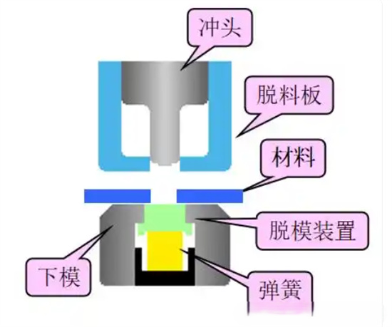
Stamping
Stamping involves applying external force to sheet, strip, tube, and profile materials using a press and a die to produce plastic deformation or separation, thereby obtaining workpieces (stamped parts) of the desired shape and size. The blank materials are mainly hot-rolled and cold-rolled steel sheets and strips. Stamping is a production technology that uses conventional or special stamping equipment to apply a deformation force to the sheet material in a die, causing it to deform and obtain product parts with certain shapes, sizes, and properties. Materials, dies, and stamping equipment (such as presses) are the three key elements of stamping. Stamping is classified into hot stamping and cold stamping based on the stamping temperature. Hot stamping is suitable for processing plate materials with high deformation resistance and poor plasticity, while cold stamping is performed at room temperature and is a commonly used stamping method for thin plates.
Stamped parts have the characteristics of being thin, uniform, light, and strong compared to castings and forgings. Stamping can produce parts with reinforcing ribs, flanges, or flanges that are difficult to manufacture by other methods, improving their rigidity. Due to the use of precision dies, stamped parts can achieve micron-level precision, high repeatability, and consistent specifications. Holes, bosses, etc., can be stamped out. Cold-stamped parts generally do not require further machining or only require a small amount of machining. Hot-stamped parts have lower precision and surface finish than cold-stamped parts but are still superior to castings and forgings, with less cutting required.
The advantages of stamping mainly include high production efficiency, convenient operation, and ease of achieving mechanization and automation. This is because stamping relies on dies and stamping equipment to complete the processing. The stroke frequency of ordinary presses can reach several dozen times per minute, and high-speed presses can reach several hundred or even thousands of times per minute. Moreover, each stamping stroke can produce a stamped part. Stamping ensures the dimensional and shape precision of stamped parts due to the die, and the surface quality of stamped parts is generally not damaged.
The die life is generally long, so the quality of stamped parts is stable and interchangeable, featuring "one die, one part." Stamping can process parts with a wide range of sizes and complex shapes, from small watch seconds hands to large automobile longitudinal beams and cover panels. Additionally, due to the cold deformation hardening effect during stamping, stamped parts have high strength and stiffness. Stamping generally does not produce chips or scraps, resulting in low material consumption and no need for other heating equipment, making it a material-saving and energy-efficient processing method with low costs for stamped parts.
However, stamping also has some issues. The dies used in stamping generally have specificity, and sometimes multiple sets of dies are required to process a complex part into shape. Die manufacturing requires high precision and technical expertise, making it a technology-intensive product. Therefore, the advantages of stamping can only be fully realized when producing stamped parts in large batches, thereby obtaining better economic benefits. Stamping also generates noise and vibration, two types of pollution, and operator safety accidents occasionally occur. However, these issues are not entirely caused by the stamping process or dies themselves but are mainly due to traditional stamping equipment and outdated manual operations.
With the advancement of science and technology, especially computer technology, and the progress of mechatronics technology, these issues will be resolved promptly and comprehensively. With the increase in plate strength, traditional cold stamping processes are prone to cracking during the forming process, making it difficult to meet the processing requirements of high-strength steel plates.
Stamping is mainly classified into separation processes and forming processes based on the process. Separation processes, also known as blanking, aim to separate the stamped part from the sheet along a certain contour line while ensuring the quality requirements of the separation surface. Forming processes aim to cause plastic deformation in the sheet without breaking it to produce workpieces of the desired shape and size. In actual production, multiple processes are often combined for a single workpiece. Blanking, bending, shearing, drawing, bulging, spinning, and straightening are several main stamping processes.
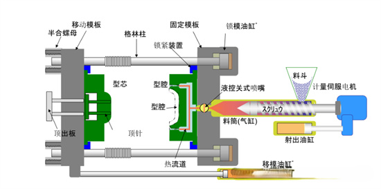
Injection Molding
Injection molding is a method for producing industrial product shapes. Products are typically made using rubber injection molding and plastic injection molding. Injection molding can also be divided into injection molding compression molding and die casting. An injection molding machine (referred to as an injection machine or injector) is the primary equipment for manufacturing various plastic products of different shapes using thermoplastic or thermosetting materials and plastic molding dies. Rubber injection molding is a production method that directly injects rubber compound from a barrel into a mold for vulcanization.
The advantages of rubber injection molding include intermittent operation but short forming cycles, high production efficiency, elimination of blank preparation processes, low labor intensity, and excellent product quality. Plastic injection molding involves melting plastic and injecting it under pressure into a plastic product mold to cool and form the desired plastic parts. Specialized injection molding machines are used for this purpose. Currently, the most commonly used plastic is polystyrene. The resulting shape is often the final product, requiring no further processing before installation or use as a final product. Many details, such as bosses, ribs, and threads, can be formed in a single injection molding operation.
An injection molding machine has two basic components: an injection unit for melting and feeding plastic into the mold and a clamping unit. The clamping unit's functions include closing the mold under injection pressure and ejecting the finished product. The injection unit melts the plastic before it is injected into the mold and then controls the pressure and speed to inject the melt into the mold. Currently, two designs of injection units are adopted: a screw pre-plasticizer or a two-stage unit, and a reciprocating screw. The screw pre-plasticizer utilizes a pre-plasticizing screw (first stage) to inject the molten plastic into the injection barrel (second stage). The advantages of the screw pre-plasticizer include consistent melt quality, high pressure and speed, and precise injection volume control (using mechanical stops at both ends of the piston stroke). These advantages are necessary for transparent, thin-walled products and high production rates. Its disadvantages include uneven residence time (leading to material degradation), higher equipment and maintenance costs. The most commonly used reciprocating screw injection unit does not require a plunger to melt and inject the plastic.
Injection molding process basics: temperature, pressure, speed. Common injection molding defects: shrinkage cavities, sink marks, short shots, flash, weld lines, silver streaks, jetting, burn marks, warpage, cracking/fracturing, dimensional deviations, etc.
AMTD provides high-precision Showerhead services for core components. Its products mainly include Shower heads, Face plates, Blocker Plates, Top Plates, Shields, Liners, pumping rings, Edge Rings, and other semiconductor equipment core components. These products are widely used in the semiconductor and display panel industries, known for their excellent performance and high market recognition.
Source: Mechanical Engineer 2023 WeChat Official Account
上一篇:In-depth Analysis of Surface Modification Technology - Anodizing Technology
下一篇:Introduction to Four Thin - Film Deposition Technologies: PVD, ALD, LPCVD, and PECVD


